Building RFID Systems With Raspberry Pi's
An Overview
So, this was an interesting problem I had to solve at work. In the garment manufacturing industry, we had a client who included an RFID tag in their price tag when their product was shipped. They wanted to use an RFID reader system to read all the tags as and when the products were being shipped so that their ERP system could be updated.
To understand the motivation for this, you need to first understand that the garment manufacturing supply is rife with pilferages. This happens especially when the cartons are being loaded/unloaded at different ports.
A result of these pilferages would be that a manufacturing company would pack the cartons with 60 pieces per carton but by the time the shipment reached the buyer, it would be short a few pieces in some cartons.
Once you have added up the pilferage cost over hundreds of shipments over the course of a year, it starts becoming a much bigger issue. Especially in today’s world of lean manufacturing, it becomes more and more important to have minimal assets moved to reduce inventory cost.
Building An RFID Reader
So, let’s first understand the difference between RFID antennas and readers.
The large rectangles you see in the image below are called RFID antennas and the smaller box you see, which is connected to the antennas is called an RFID reader.
The antennas are just dumb boxes which are constantly sending out an RF wave and picking up data from tags which are present.
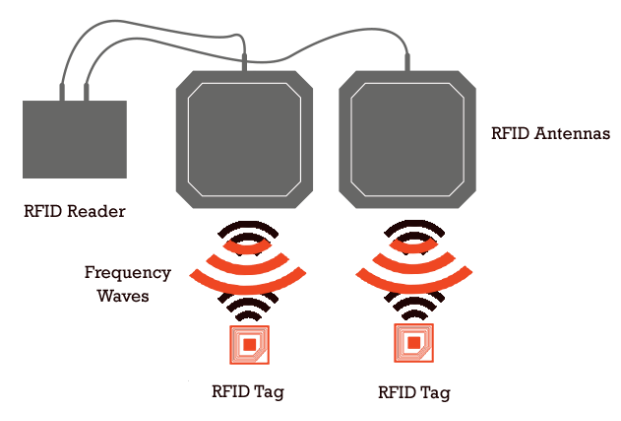
The reader, on the other hand, is the “smart” box. The CPU of the system, if you will. It picks up the data from the antennas and depending on the sophisitication of the reader, will pick out the actual RFID tags, get rid of the dummy / redundant data and return the tags in a neat list.
However, the sophistication of the reader is highly dependent on the brand manufacturing the reader. Zebra, as always, is at the top of features and price.
There are plenty of other brands that provide RFID readers ranging from Zebra and Chainway all the way down to nameless RFID antennas that have no brand name which are manufactured in China.
I, unfortunately, had the experience of working with a nameless brand from China.
The Issue Of Branding
You might think that branding is actually not that big a deal when it comes to RFID antennas and readers. However, it turns out to be a very big deal, especially for someone inexperienced dealing with hardware of this kind.
A lot of brands that sell RFID readers and antennas on sites like AliBaba tend to sell a combined reader and antenna. This means that you get an antenna with the reader built into that.
This becomes a problem when you need more than one antenna, because now you suddenly have to deal with two readers. All the benefit of having one reader is now suddenly gone. You have no system taking the cognitive load off your system. All that complexity falls in your lap.
The Physical System
The physical system comprised of the following:
- A barcode scanner
- A weighing scale
- Two RFID readers/antennas
- Raspberry Pi
- Cooling system for the Raspberry Pi
- Monitor
- GPS system
The weighing scale was a double check to make sure that the number of garments packed in the carton made sense. For instance, it could be easy to cheat the system if you just tossed the RFID tags in the carton without the associated garment.
However, the weight would be a double check to ensure that this approach couldn’t always cheat the system.
The barcode scanner requires some business context to first explain. The client used two types of cartons - perforated and non-perforated.
The client also had three different types of packing they allowed - solid, mixed and assorted.
Solid cartons have all garments of only one size. Assorted cartons have garments in a ratio like the below
S	M	L	XL
1	1	1	1
Mixed cartons imposed no such restrictions and allowed any mix of packing.
Non-perforated cartons allowed only for assorted packing whereas perforated cartons allowed for the remaining two.
So, the barcode scanner was being used to determine whether the carton was perforated or not. Each carton had a barcode that either ended in P or without a P. A P indicated that this carton is a perforated carton.
The cooling system was something I realised we needed after testing out the system on the physical location. Unfortunately, Raspberry Pi’s are not designed for industrial use cases as they tend to get very warm after running at a certain capacity for an extended period of time. The cooling system was just a safety measure to make sure the Pi wouldn’t blow up and ruin the whole system.
Since we were deploying in 13 different locations, it made sense to set up a GPS system hooked up to the Pi which would return the latitude and longitude, which the Pi then checked against a server to determine what the location is.
The Digital System
Understanding And Reading RFID Tags
The RFID antennas I was trying to read from had an RS-232 cable and since the Raspberry Pi only has USB ports, the first thing I needed was an RS-232 to USB converter. These are pretty cheaply available but the cheap ones would come back to bite me later.
Reading from a serial port using Python on a Pi is pretty straightforward. You just need to enable the serial interface and you can start reading using code like serial.Serial(
'/dev/device-name', 57600, timeout=0.5)
But, the real complexity comes in when you’re reading from two devices at the same time and they are both sending bytes constantly at the baud rate specified.
The first thing that helped read the data was realising that the readers are sending a 17(0x11 in binary) to indicate the beginning of a tag and send 18 bytes following that indicating what the tag value is.
So, code like this helped understanding what was going on
read_bytes_from_device_1 = self.serial_device_1.read()
            int_value_from_device_1 = int.from_bytes(
                read_bytes_from_device_1, "big")

            read_bytes_from_device_2 = self.serial_device_2.read()
            int_value_from_device_2 = int.from_bytes(
                read_bytes_from_device_2, "big")

 if int_value_from_device_1 == 0x11:
                should_read_tags_from_device_1 = True

            if should_read_tags_from_device_1 is True:
                tag_bytes_list_for_device_1.append(int_value_from_device_1)

                # One RFID tag has a sequence of 18 bytes
                if len(tag_bytes_list_for_device_1) == 18:
                    should_read_tags_from_device_1 = False
                    self.read_tag_data(
                        tag_bytes_list=tag_bytes_list_for_device_1)
                    # Clear the bytes from the RFID tag read in preparation for the next one
                    tag_bytes_list_for_device_1.clear()

            # The starting byte of any tag id is 0x11 (which is 17)
            if int_value_from_device_2 == 0x11:
                should_read_tags_from_device_2 = True

            if should_read_tags_from_device_2 is True:
                tag_bytes_list_for_device_2.append(int_value_from_device_2)

                # One RFID tag has a sequence of 18 bytes
                if len(tag_bytes_list_for_device_2) == 18:
                    should_read_tags_from_device_2 = False
                    self.read_tag_data(
                        tag_bytes_list=tag_bytes_list_for_device_2)
                    # Clear the bytes from the RFID tag read in preparation for the next one
                    tag_bytes_list_for_device_2.clear()
There’s obviously a lot of context missing from this code, but this is the gist of what the system was doing.
When the data from the tag is read, it appears as something like this: 303ACA4782A055999C82CF9D. This is called an EPC tag and each of these codes is unique to one RFID tag. This is a hexacdecimal value made up of 24 digits where each digit represents 4 bits. So, converting into binary would give you 001100000011101011001010010001111000001010100000010101011001100110011100100000101100111110011101.
Here’s what different segments of that code break down to
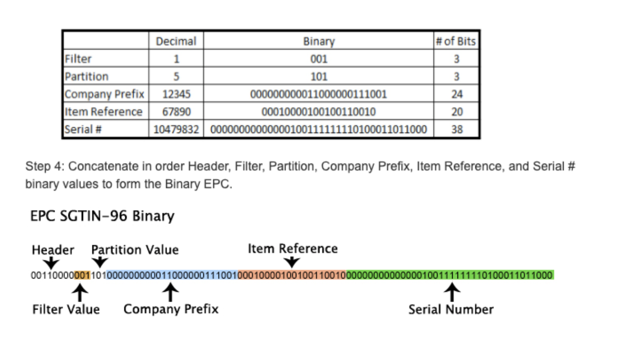
The item reference points to a specific SKU that this tag is associated with and the serial number points to a specific instance of that SKU.
Reading Data From The Weighing Scale And Barcode Reader
This was a lot easier to do once I figured out how to read data from the RFID reader.
The process was the same with the weighing scale which had an RS-232 cable. With the same converter, it was possible to read data directly from the Pi. The only tricky part with the weighing scale was realising its sending data back as a string, which needed to converted and also understanding the hardware configuration of the weighing scale, like what baud rate the scale sends data at.
The barcode reader required certain permissions on Linux since it was a HID device, but that was straightforward to do with udev rules on Raspberry Pi OS.
Visibility Into The System
One of the main concerns of mine before deploying the system was wondering how to diagnose issues with it.
Since it was deployed across 13 different locations, it would be a nightmare for me to try to debug it remotely by talking to someone. And trying to remotely login to the system would be a massive security risk so I couldn’t use that approach.
Eventually I settled on just using logs on AWS through CloudWatch.
I thought it would be fairly easy to do this but doing it reliably when the entire system was running with multiple processes turned out to be quite challenging.
The problem with multiple processes is the order of the logs makes no sense since you run into race conditions, if you log everything into one file.
The approach I finally settled on was the one mentioned in this issue which requires a worker process to set up a separate queue per process and log it with the specified format.
The format I used was formatter = logging.Formatter(
'%(asctime)s %(name)s %(levelname)-8s %(message)s')
Updating The System
The next issue was updating the system since it was deployed across multiple locations, it made no sense to travel to each location and update the system manually.
Managing servers with AWS is straightforward now but managing on prem instances, especially if they’re running a Raspberry Pi OS turns out to be a little tricker.
I’ll give a brief gist of what I did but a more detailed explanation can be found in this README file.
First thing is to set up the Raspberry Pi as a managed on-prem instance with AWS SSM. This allows you to have visibility into the current status of your servers, whether they are online or offline or whether they have a running deployment.
The next thing is to set up the AWS CLI on the Raspberry Pi and then install the CodeDeploy agent on the Pi. This turned out to be the trickiest bit because setting up Raspberry Pi OS with the CodeDeploy agent requires some workarounds that aren’t very well documented.
Running The System
The next step was to figure out how to daemonize the whole system so that the program runs on startup and does whatever configuration is required, even if it is a fresh Raspberry Pi hardware.
For this, I ended up using SystemD, which is the standard daemon tool Linux ships with. Here’s the code for the unit file
[Unit]
Description=Pi RFID Service that will boot to GUI
Wants=network-online.target
After=network.target
StartLimitIntervalSec=0

[Service]
Environment=DISPLAY=:0
Environment=XAUTHORITY=/home/pi/.Xauthority
ExecStart=/home/pi/pi-rfid/pi-rfid-virtual-env/bin/python3 /home/pi/pi-rfid/RFID_Upload_V0.2.py --env production
Restart=always
RestartSec=1
KillMode=control-group
TimeoutSec=infinity

[Install]
WantedBy=graphical.target
This documents all the different requirements before the program will boot. For instance, the wanted by sections will indicate that the system needs to be connected to the internet and a monitor needs to be detected before the ExecStart function will run.
Finally, the UDev rules for the system indicate how the hardware connections need to be configured
# This rule is meant for the USB barcode scanner
SUBSYSTEM=="hidraw", ATTRS{idVendor}=="0483", ATTRS{idProduct}=="0011", MODE="666", SYMLINK+="usb-barcode-scanner"

# This group of rules is meant for ttyUSB devices which are plugged into different physical ports
KERNEL=="ttyUSB*", KERNELS=="1-1.3:1.0", SYMLINK+="rfid-reader-1"
KERNEL=="ttyUSB*", KERNELS=="1-1.1:1.0", SYMLINK+="rfid-reader-2"
KERNEL=="ttyUSB*", KERNELS=="1-1.2:1.0", SYMLINK+="weighing-scale"

# This group of rules is a test meant only to see if inserting a usb drive into different
# physical ports will create a different symlink
KERNEL=="sd*", KERNELS=="1-1.3:1.0", SYMLINK+="usb-stick-3"
KERNEL=="sd*", KERNELS=="1-1.1:1.0", SYMLINK+="usb-stick-1"
KERNEL=="sd*", KERNELS=="1-1.2:1.0", SYMLINK+="usb-stick-2"
The UDev rules are important because when the system is being installed, there shouldn’t be a dependency on an engineer to go there and configure the system in an exact manner. I wanted to set it up so that anybody could install the system with bare minimal instructions.
So, in the rules, you can see that symlinks are created based on which port the RS-232 to USB cables are plugged into the Pi. It still requires that the devices are plugged into specific ports but it doesn’t require anything beyond that.
Stitching The System Together
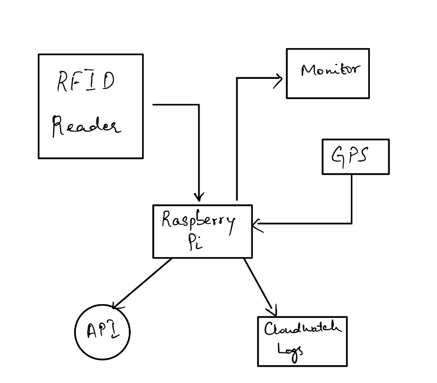
The image above shows the different components of the system. There are a few not mentioned like the weighing scale and the barcode reader.
Each of the subsystems run in a separate process and send their logs and make API calls using a central service as and when required.
Learnings
The biggest learning for me was from implementing this entire project was that hardware is very, very complicated. Everything detailed in this blog post took me months to figure out.
Dealing with hardware becomes doubly difficult when you either lack experience with the hardware (obvious) or when the hardware specs are poorly documented. Cheaper hardware tends to be more poorly documented than name brand hardware. When dealing with hardware, it’s almost always worth paying the premium for a brand just because of the associated documentation.
For instance, here is Zebra’s support page for their FX9600 RFID reader. They provide SDK’s for major programming languages and platforms. All of Zebra’s SDK’s probably use something like LLRP (low level reader protocol) for their readers to read the data from the RFID tags. This makes it much, much easier to read data from the tags because you don’t have to worry about collisions between different tag data and checking the parity bit to ensure that the data you are reading actually belongs to the tag you started reading for.
Notes
I have open-sourced the code for this system. You can find the source code here. I hope it can be of use to someone who finds that they are faced with similar problems.